Evolution Motorcyles, Inc


Evo-Moto


Evolution Motorcycles, Inc. will be manufacturing the next step in the evolution of electric motorcycles
Images shown are stock images downloaded from the internet. Evolution Motorcycles design is still in stealth mode but will be shown here when available.
As you may have guessed from the login page, we believe that one of the biggest things in the future of electric motorcycles lies in the donut motor, or hubless design.
Removing the motor from the frame and putting it into the hub creates space in the frame structure for other items. It also reduces complexity with no chain and sprockets (and the dampers which go with them) or other final drive parts, It also reduces power losses due to mechanical inefficiency and simplifies overall maintenance.
Finally, the amount of sprung weight can be further reduced increasing stability, control, rider safety and comfort.
The video above is the first successful test of the benchtop motor configuration which is to be used on our Technology Demonstrator.
It utilizes two 12v lead-acid batteries with conventional off-the-shelf (OTS) drivers and parts. Some of the cabinetry was 3D printed for convenience but otherswise all zero-risk stuff.
Please note that the noise is being generated by the 3D wheel parts scraping the structural carriage. Extremely low cost (and noisy) 18" lazy-suzan bearing ($45) was also used.
Meanwhile, in the shop I managed to build a full sized 18" motorcycle rim with the same controls as the benchtop prototype and have it functioning.
Several things to note:
1. The rim is 3D printed in 4 sections (due to it's size) and bonded together. Which makes it noisy. The one shown above is not production material due to cost concerns (production Carbon-Fiber material is 3x more expensive so will be saved for strength testing);
2. This is still a benchtop prototype, just in a production format. The magnet ring is held in place by non-permanent methods due to occasional dis-assembly for various R&D reasons;
3. Although this rim isn't intended to be used on the technology demonstrator due to strength concerns, it can mount and carry a standard 150/70-R18 motorcycle tire which is the next step.
We originally envisioned purchasing a donor bike to mate our system to. However, prices for the preferred model stayed unreasonably high and we decided to go another way.
We have designed and are fabricating our own prototype for this stage of the project. The donor bike route was always going to take a significant reverse engineering effort, and we decided that we can get better budget and schedule by hybridizing the prototype motorcycle to a greater degree than would have been necessary with the donor bike concept.
Originally, using an existing motorcycle as a donor gave us some advantages. The donor bike would have been stree t legal, making it easier to perform riding tests on the street. As the new demonstrator will not be legal to ride on the street, we will necessarily be spending more time at the track proving out the design. Which was part of the plan anyway, it just became more important.
We are taking several key components from a 2019 Kawasaki Z400 and integrating them with chassis parts fabricated in-house. Front forks, wheel, tire, brakes, triple clamps and hand grips have been purchased used from eBay. A used rear suspension and mount system (shown below) has been purchased, again from eBay. The swingarm (shown below) has been scanned into Solidworks and modified to carry the new rear wheel and motor. Rider footpegs and side stand have also been purchased.
Several rear swingarms have been aquired and will be modified to carry the new motor. The image to the right shows the rear suspension system and linkages of the stock Z400. The plate to the far right mounts to the back of the Z400 motor (which is a structural member) and then into the frame


The image to the left shows a partial stock swingarm (3D scanned into SolidWorks with a spiffy handheld) mated to the 3D printed swingarm adapters and then to the motor/wheel combo.
The video to the right shows the completed rim/motor/tire combination mounted to the Z400 swingarm. The unit is ready for advanced testing which will include several rims being tested to destruction.

All of these parts will be integrated to a full monococque chassis (CAD image below) with electronics under the seat and battery pack in the chin fairing for low CG. Not shown are front and rear suspension systems. Those are validated as explained below.
The last step for the demonstrator is to perform strength tests to insure the safety of the in-house manufactured parts. This includes pressure testing the rim/magnet assembly and strength testing the monocoque structure.
The pressure test consists of mounting the tire to the rim/magnet assembly, submerging it in a water bath for safety, and inflating the tire to insure it can hold operating pressures.
Strength testing of the structure includes complete assembly, and then statically adding weight to a pre-determined amount to insure integrity.

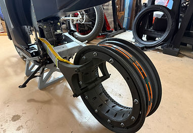
The above photos show the chassis with front tire and rear rim/motor. Front and rear suspension components are installed to validate the accuracy of the reverse engineering effort. Next step is to mount the rear tire and begin aforementioned testing. Broken stuff will appear on this page as well.
We finally managed to get the tire mounted to a one-piece, 3D printed rim. In order to get a rim from a single print job, we had to get a bigger printer (more on that later). After re-assembling the bike with the new motor/rim/tire assembly, the testing has (so far) gone largely as expected.

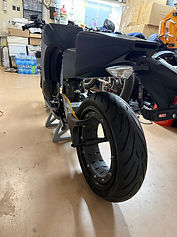

In the video above ( in case you didn't hear me say it) the motor is being driven by the benchtop controller (no bike electrical system yet). After that is created and installed, we might actually get a ride in. Shortly after that, we'll start to do some destructive testing on rim and frame parts.